Modeling diagrams in Dawiso let you visually represent data and its relationships through fully customizable diagrams. You can create new entities directly in the diagram or add existing objects from your environment by searching and dragging them into place.
Objects can be connected using notations such as crow’s foot and styled with shapes and colors to reflect their type or role. This flexibility allows you to adapt diagrams to a variety of modeling needs, such as:
- Conceptual models to capture high-level business relationships.
- Semantic models to clarify meaning and context.
- Logical models to describe entities and attributes in greater detail.
Available elements are relations will depend on the diagram configuration. For example, diagrams for semantic models will have a different selection from logical models.
Unlike lineage diagrams, which show how data flows and transforms across systems, or entity relation diagrams (ERDs), which focus on the structural relationships between database entities, modeling diagrams are fully customizable. They are not limited to technical dependencies and can include any objects you choose to represent, linked in ways that best reflect your use case.
Create a model
First, make sure your application has an object type that supports modeling diagrams. Admins can add object types that have the create_as_diagram feature to applications. For more information, see Object Type Features.
- In your application, click Create in the top navigation bar.
- Name the object and select Diagram object type.
- You will get redirected to the diagram creation page.
Add objects and elements
Modeling diagrams are fully customizable. In the edit mode, you can add or remove objects, new elements, and relations between them.
The left-side menu displays Diagram objects by default. Click any object or element to quickly center the view on it.
Objects
First, add objects to your model. You can add the same object multiple times. Frame color and icon of added objects are based on the package configuration.
Add objects to diagrams using the following methods:
A. Action panel
- In the Action panel in the middle-bottom of the diagram, click + Add object.
- Look your object up. You can use facets to filter your results by clicking the funnel icon on the right.
- Click Confirm to add it.
B. Left-menu hierarchy
- In the left-menu, switch to the All objects tab.
- Select which Space and Application you want to add objects from. If needed, use the search bar to look up a specific object.
- Identify your object and drag and drop it to the diagram.
You can add objects from various spaces and applications to the same diagram.
Right-click an object to open its context menu. From here, you can:
- Open the object detail.
- Open another diagram type associated with the object (such as a lineage diagram or ERD).
- Open the object page in a new window. You can also easily:
- Copy-paste an object.
- Delete an object.
- Bring the object to the front or send it to the back.
Elements
Apart from objects, you can also add custom shapes as elements to your diagram.
- In the Action panel in the middle-bottom of the diagram, click the arrow next to Create and select your shape.
- Add the shape to the diagram.
The following shapes are available:
Resizing or moving a folder element to fully fit another element will create a parent-child relation between them, this means that e.g., Object A will belong to Folder 1.
Similarly, moving an element to another folder will automatically change its parent.
Change element background color
To change your and object’s or an element’s background color:
- Select your object.
- In the small menu that appears near the element, click the circle icon and select the new background color.
Relations
Add a relation
Relations between elements can be added in two ways, directly in the diagram, or using the action panel.
Connection handles
- Select an element. Each element has connection handles displayed on the top, bottom, left, and right sides of the element. When you hover on them, they turn into icons.
- Click and hold a handle.
- Drag the line to another element.
- Release to create a relation between the two elements.
Action panel
- In the Action panel in the middle-bottom of the diagram, select the line icon. Or click the arrow next to the line to select a different relation type.
- Click and hold the source element.
- Drag the line to the target element.
- Release to create a relation between the two elements.
Edit relations
When you click on a created relation, a menu will be displayed, allowing you to edit it.
| Action | Description |
|---|---|
 Change color Change color | Click the circle button to change the color of the line. |
| T Add text | Click the text button to add text label to the line. |
 Change relation type Change relation type | Select relation type for your relation. Currently, the following types are available: 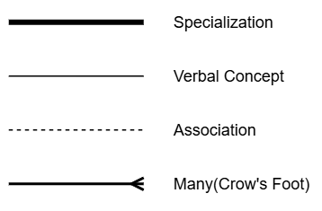 |
 Choose relation style Choose relation style | Select line type. You can choose between rounded or sharp edges. Not available for Many relation type. |
| Line start | Choose whether the line should display an arrow at the start. Many (crow’s foot) relation type has the following line notations available: 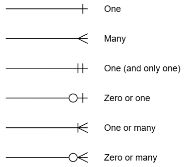 |
 Swap Swap | Click the swap icon to switch the line start and line end. |
| Line end | Same options as for the line start, but applied to the line end. |
| Delete | Click the trash can icon to delete the relation. |
You can also adjust the path of relation lines. When you click a relation line in a diagram, manipulation handles appear:
 Thick line handles: Move sections of the line up, down, left, or right.
 Circular end handles: Mark the points where the line changes direction. Dragging them lets you adjust the angle or move the bend to a new position.